 Loading product data...
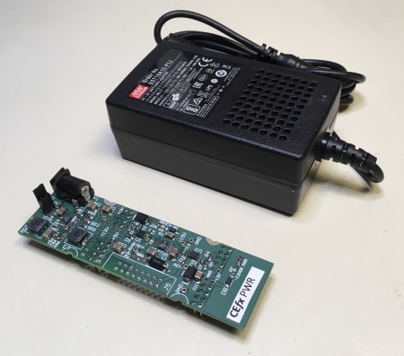
It is best to install the PWR module before the other modules, to make sure that the module is functioning properly. Once installed, plug in the 15V power supply. When the 15V power source is on, you should see three green LEDs on the PWR module.
The order of the buses from rearmost to frontmost is +12V, +5V, ground, and -12V. Watch out for breadboards with split buses -- you can identify them because there is a wider-than normal gap between the buses on the left and right of the breadboard. You can use these breadboards by simply straddling the middle gap with the PWR module or any other CEfx module, or installing 4 jumpers to link the two sections of breadboard.
Once you've verified three green LEDs, turn off the 15V power supply, wait for the LEDs to turn off, and install the other CEfx modules. Be careful to install them right-side-up -- the front and rear edges should align with the power supply edges. Controls are in the front and cables (if any) go out the rear.
Turn on the 15V power again, and again make sure that the three LEDs are on. If one or more LEDs is off, immediately disconnect power and investigate. To troubleshoot, try removing all but one CEfx module and powering up, then adding modules back in until the problem returns. Always remove power to the PWR module before installing or removing CEfx modules.
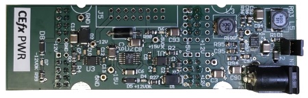
The CEfx-PWR module is capable of supplying 5V at 700mA, +12V at 120mA, and -12V at 80mA. This is more than enough for one solderless breadboard, and usually enough for two or more. For setups where you don't need the +5V supply, it is a good idea to remove "5VEN" jumper near the rear of the module. This will disable the 5V regulator, removing a potential source of high-frequency noise.
If you use a very small amount of +5V (less than 10mA), you can reduce noise by adding a 500Ω resistor to the breadboard between the +5V and ground buses. This guarantees a minimum current from the 5V regulator and quieter operation.
Loading product data...
Loading product data...
Loading product data...
The TPS7A4901 adjustable regulator was choosen for the +12V line. It has excellent noise specs and low dropout voltage, but its a bit small physically, which limits its ability to dissipate power. The regulator is specified to work at 150mA, which is plenty for ten or more CEfx modules. We specify 120mA for this module to give a bit of margin, and keep the chip temperature in the touchable range.
Although the TPS7A4901 behaves well with a variety of loads, it can produce a 5 MHz oscillation when the main load capacitor C3 is too far away from the IC. C2 suppresses the oscillation.
It would be possible to get the +5V with a linear regulator from the +15V, but future CEfx modules wil likely include microprocessors and DSP chips which may require upwards of 500mA. At that current, a linear regulator would dissipate 5 watts, which would require a large heat sink. A switching regulator will dissipate much less, but must be designed carefully to keep high-frequency noise out of the +5V and ground lines. We use the LT8609 for this purpose which has extremely low switching noise. The design is taken mostly from the LT8609 datasheet (Ultralow EMI 5V 2A regulator).
The only issue with the LT8609 is that it generates 20mV of ripple at 2.5 KHz if the +5V load is less than about 10mA (not a good frequency for audio). The problem goes away when the load is above 10mA, so for lightly loaded applications, the regulator will work best with a 500 Ohm resistor placed between the 5V line and ground.
The regulator is capable of generating 2A, but the inductor used for the post-filter saturates well before that. And even before saturation it drops enough voltage to lower the output voltage to about 4.75V at 1A. So we specify the max current at 700mA, which is more than we expect the CEfx modules will need.
For the -12V there was a choice of two different kinds of inverting regulators: inductor-based, and switched-capacitor. The latter is usually quieter, but can't provide as much current as the inductor version. Since we don't expect to need much -12V current we went with the capacitor-based LTC3261. That is followed that with the TPS7A3001, the negative brother of the TPS7A4901 we use for +12V.