Loading product data...

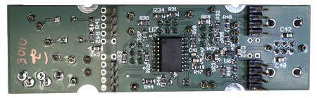
For stages 2-4, you select between low- and high-pass modes with jumpers. The stage 2 jumper set is closest to the rear of the board, then stage 3 jumpers in the middle, and stage 4 jumpers closest to the front controls. The CEfx VCF ships with the filter stage jumpers set to low-pass, with three shunts installed on each jumper set.
Note the "LO" marked on the silkscreen next to each shunt. To reconfigure a stage from low-pass to high-pass, remove all three shunts, then replace one shunt next to the "HI" marking on the silkscreen.
Pics to come...
To configure the VCF to be a 4-pole high-pass filter, you will need to reconfigure all three jumper sets, and send the input to IN HI.
For a bandpass filter, set STAGE2 to high-pass, STAGE 3 and STAGE 4 to lowpass, and send the input to IN HI. Note that a bandpass filter will self-oscillate when the RESONANCE knob is set higher than about 12 o'clock. This can be used to create a voltage controlled sine-wave oscillator. Increasing RESONANCE further will add harmonics to the sine wave.
To create a useful low-pass/band-pass hybrid filter, set all three stages to low-pass, and send the signal into IN HI. It is generally a good idea when mixing high-pass and low-pass stages to put the high-pass stages first in the chain. That way, the following low-pass stages can remove any high-frequency noise created by the circuit itself.
As shipped, the frequency-setting capacitors (C35 - C38) are identical (330pF), which means the corner frequencies of the four stages will also be identical. However, these capacitors are socketed, which allows for experimenting with alternative frequency responses. Stay tuned for suggestions.
The audio output has a source impedance of about 1KΩ. It is available on the "OUT" testpoint and the "TIP" connection of the phone jack.
There are two Control Voltage input testpoints, labeled CV IN1 and IN2, just above the FREQ OFFSET potentiometer. In between them is a testpoint labeled "POT", which is the output of the "FREQ OFFSET" potentiometer. The voltage on the POT testpoint will vary between +5V (FREQ OFFSET fully counterclockwise) and 0V (FREQ offset fully clockwise). Normally, the POT testpoint is shorted to IN1, leaving IN2 available for external control voltages, but you can remove the short to allow two external voltages to control the VCF. The voltages at IN1 and IN2 are summed together to create the final control voltage.
Two important points about the frequency CV inputs. First, _increasing_ voltage _decreases_ the corner frequency, which is the opposite of how a VCO works. Second, the input sensitivity is 2 octaves per volt instead of one. This was done to give a bit more sensitivity to control inputs. To reduce the sensitivity to 1 octave/volt, add a 49.9 K resistor in series with your CV source. To increase sensitivity, send your CV source to both CV inputs.
Filter resonance can be controlled by a voltage between 0V and +5V. Normally, this voltage is supplied by the RESONANCE potentiometer, but it is possible to use an external control voltage. To do this, remove the short marked "RES" above the RESONANCE pot, and inject the control voltage into the testpoint closest to the rear of the module (and C44). Resonance sensitivity varies dramatically with filter type. It usually isn't possible to get a four-stage low-pass filter to self-oscillate even with resonance all the way up, but a bandpass filter will oscillate with RESONANCE at the halfway point.
The max audio input level is about 6Vpp with resonance turned down. As resonance increases, it adds gain to certain frequencies, so you may need to reduce the input level to avoid clipping.
For three of the four stages there is an arrangement of headers such that a user could select low-pass or high-pass functionality by repositioning shunts. As can be seen in the schematic, the shunts simply rearrange the RC network at each stage. For the first stage, the user chooses between low- and high-pass by simply changing the audio input.
Stay tuned for a design note that use the all-pass settings to create a phaser.