The Cabintech CT3680 is a hybrid module that implements from 1 to 4 flexible, configurable audio delay lines with up to 2.7 seconds of delay time. This module can be used by system designers to create many different delay-based effects (reverb, echo, chorus, flanger, etc.) using traditional analog feedback paths, filters, and modulation techniques. Although the CT3680 is digital at its core, all inputs and outputs are analog -- no programming or digital logic design is required and it integrates easily into an analog signal flow. The CT3680 uses a fixed sampling rate that is independent of delay time, producing consistently high quality audio at any delay setting with a S/N ratio of over 92dB and THD of less than 0.0009% across the full 20Hz to 20kHz range.
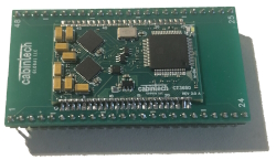
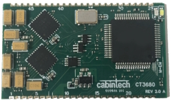
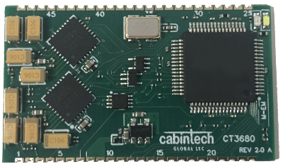
The CT3680 is easy to use with simple analog audio inputs and outputs, control voltages to set parameter values (such as delay time), and a single +5V power supply. The small module size (22x38mm, 0.9”x1.5”), surface mount edge pins, and through-hole adapter options provide flexibility for mechanical fitment into small spaces and optimize the use of PCB board space.
The CT3680 is designed to minimize external component requirements and integrate easily to PCB effects designs. The CT3680 requires no external clock and is powered by +5V. All CV signals are +3.3V maximum (see Specifications and Maximum Ratings in the Reference Guide). A +3.3V reference is made available on an output pin to aid in generating CV signals. All audio analog inputs and outputs are single-ended, 2.5V full scale, and AC coupled. Clipping is detected and signaled on an output pin and an onboard LED.
The physical package is a 48 pin surface mount castellated edge pin module. It can easily be hand soldered or soldered in automated systems. A 48-pin standard DIL spacing through-hole adapter is available for through-hole PCB designs.
The CT3680 has 4 analog audio inputs, and 4 analog audio outputs. The relationship between the inputs and outputs and delay times is controlled by the selected configuration settings. All audio inputs and outputs are line level (2.5V peak), single ended AC coupled for easy integration into an analog signal chain. Traditional analog effects circuits with filtering, modulation, and gain control can be used to create feedback paths for various types of effects.
The configuration options control the number of independent delays lines (“channels”) and the maximum delay times they have. Each channel has 1 audio input and 1 or more outputs. Each output has an independent delay control. For example, a channel with 2 outputs would have one input and two outputs. The outputs are both delays of the same input, but with different delay times, each controlled with a separate CV (control voltage). There are many possible configurations of channels and outputs. For example, one of the configurations is 2 channels with 2 outputs each:

In this configuration, output 1 will be a (variable) delay of input 1. The amount of delay at output 1 is set by a control voltage (CV-1). Output 2 is also a variable delay of input 1, with its own control voltage (CV-2) which sets the delay of output 2. The delays at outputs 1 and 2 are both of the same signal (input 1) but are independently variable. Likewise, outputs 3 and 4 are independent delays of the signal at input 2, controlled by CV-3 and CV-4 respectively. A configuration like this might be used in a true-stereo effect that requires 2 separate channels of delay.
Another configuration consists of 3 independent delay lines, 2 of which have a single delayed output, and 1 has two delayed outputs:

The different configurations can be useful for constructing different types of effects including stereo and effects that utilize multiple delay lines.
Configuration is done with 4 input pins that choose between different “programs”, each of which defines a specific configuration. In addition, 5 “option” input pins control additional features depending on the selected program. See Program Selection in the Reference Guide for a description of all the available programs.
Additional inputs select the audio sampling rate (48kHz, 32kHz, 24kHz, 12kHz). Lower sampling rates allow for longer delay times. The sampling rate remains fixed at the selected rate (e.g. sampling rate is not used to vary the delay time as in traditional BBD devices). (See Sampling Rate Selection in the Reference Guide)
The selection of configuration and sampling rate defines the minimum and maximum delay of each channel in the configuration. The outputs for that channel can have any delay time between the min and max, and the delay time can vary dynamically by use of control voltages (CVs).
A delay CV is an input voltage in the range of 0.0V to 3.3V. When the CV is at 0.0V then the corresponding output is at the minimum delay. When the CV is at the maximum of 3.3V then the output is at the maximum delay. Voltage levels between 0.0 and 3.3 form a linear scaling of delay time between min and max. For example, the following configuration has 1 channel with 4 outputs controlled by CV-1 through CV-4. With a sampling rate of 48kHz this channel has a max delay of 682ms and a min delay of 0.3ms.

With the control voltage values shown, the outputs have the delays shown. Note that the lines as drawn in the diagram are conceptual and not drawn in proportion to the actual delay time. E.g. the line for output 1 is drawn to the right of channel 2 on the green channel bar (closer to Max delay), but actually has a shorter delay time. The CV for any output can select any delay time in the range from min to max, independent of all other outputs.
For more details and examples, see Setting Delay Times in the Reference Guide.
Some programs (configurations) support additional features. These features are optional and enabled using the 5 OPTION input pins. See the individual program descriptions to see what features are supported in which programs.
See the in the Reference Guide for complete specifications, configuration options, additional features, and design notes.
For effects developers familiar with traditional BBDs, the CT3680 provides emulation of all current-production BBDs and many BBD chips long since discontinued. Effects design is similar to BBD circuit design but with more flexibility, capability, and much higher fidelity especially at longer delay times.
A full set of tools are available to speed up your effects design including a development board, a detailed datasheet and design guide (in the Reference Guide), adapters to accommodate through-hole PCB designs, 3D models, PCB footprints and more. See below for documentation links and development support products.
Design Aids
Schematic symbol and PCB footprint
3D models
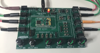
The CT3680 development board provides a platform for prototyping and development of CT3680 based products. The board supports all features of the CT3680 with switches, potentiometers, and 2.5mm jacks for all inputs and outputs of the CT3680. This allows for operation of all features of the device with no external circuitry. All on-board controls can be disabled and made available on header pins for off-board operation of program selection, option settings, control voltages, and multi-module linking.
This adapter converts the CT3280 into a 48-pin through hole device suitable for use in breadboarding or through-hole PCB designs.